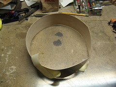
 | I used wide masking tape to hold the ends of the duct together. Masking tape is used for two reasons. First, it is easy to tear while maintaining tension on the ring. Second, the glue should bond to it well. |
 | Two strips to start, pulling the edges together well. |
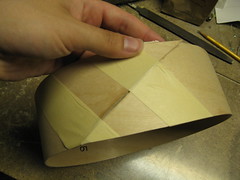
 | All taping complete. |
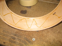
 | Inner side showing completed tape. |
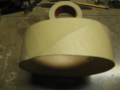
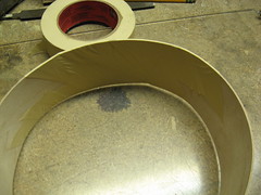
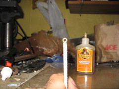
 | Using Gorilla glue to hold the rings together, because the Testor's I use for the rest of the craft dries too fast. |
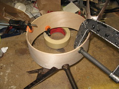 | Lots of clamps to hold the thing tight while gluing, especially the seams. |
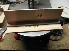 | Aft panel and aft top panel being glued with Testor's quick-dry wood glue. |
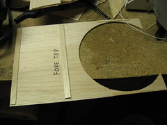 | The lid was fairly weak across the width, as that is perpendicular to the grain. I took a couple strips of scrap balsa and 1/16" plywood and glued them down. The strip in the back is to catch the screws for the hinges. |
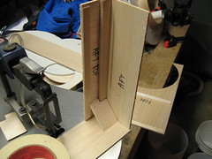 | More Testor's, this was fully set before the picture was finished saving to SD card. The thick piece of wood is a chunk of oak I had from a different project--I ended up cutting the aft panel 1/8" too narrow and needed to fill the gap. The strip of 1/16" plywood in front will catch the screws for the hinges. |
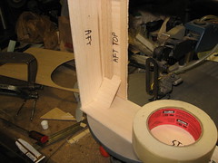 | Another fast set. I love this glue--it is essentially superglue (the first ingredient listed is cyanoacrylate) but somehow designed for wood--it does not stick fingers together, and seems to avoid most other surfaces as well. |
 | Completed superstructure, less one duct. |
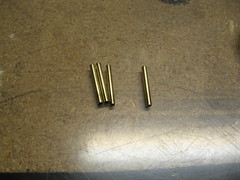 | Some 1/8" ID brass tubing I had laying around. 1.5" long, polished on a wire wheel to give the Gorilla glue something to grab and act as the hinge barrels for the rudders. |
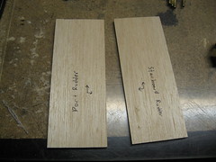 | Rudder blades. Markings are to orient them vertically and horizontally, so when I start adding control horns, there are no mistakes. |
 | Aligning the barrels. |
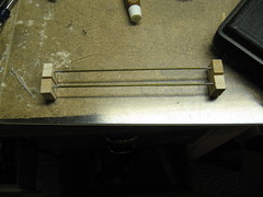 | The support blocks and rods the rudders will swing on. The rods are straightened sections of coathangers, the ends have been cleaned with a wire wheel for glue to grip. |
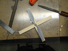
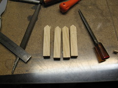 | Four pieces of wood will mesh together to form a cross-shaped support for the lift motor. |
 | Mesh is acceptable, on to size test. |
 | The support is the right size--a little extra (1/8" total across the blades) to allow for shaping to fit the duct, and the minimum clearance for the tips. |
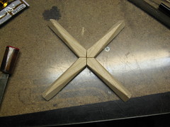 | A bit of shaping to make the support more aerodynamic. Mostly done on the scroll saw with the table tilted, then rounded lightly with a wood rasp. |
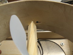 | A small hole drilled along one support strut for the motor leads to go through. The support was fit into the duct by mostly brute force, pushing three of the four legs in first and then flexing the duct out and around the fourth, then adjusting position slowly. Once positioned, some Testor's was put in a fillet around the leg. |
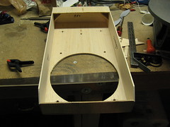
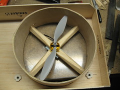 | Completed duct in the superstructure. A little expanding foam will be used to fill the gaps left, since the hole is perfectly round and the duct is not. |
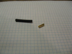 | Female bullet connector on the right, heatshrink to cover it on the left. |
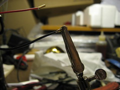 | Soldering the bullet connectors to the ESC leads. |
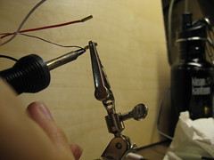 | This joint needs to be not only solid but also relatively low resistance, to deliver stable power to the motor. |
Also, I did another test of the lift motor, now in its duct:
Video on YouTube
No comments:
Post a Comment